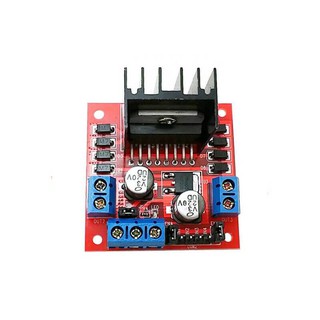
OUT1: DC motor A + terminal; OUT2: DC motor A terminal; OUT3: DC motor B + terminal; OUT4: DC motor B terminal; At the bottom you have a three terminal block with +12V, GND, and +5V.The +12V terminal block is used to power up the Arduino unipolar stepper motor control code: can you provide sketch for max speed test for nema 34 and 23 114 mm. I used teensyduino to write a little arduino-like sketch to control the stepper motor.

The main target is additive fabrication using FFF processes. 1.6 Fixed a problem with wrapping of microsecond stepping that could cause stepping to hang. IN3 and IN4 control the direction of the motor connected to OUT3 and OUT4. Only one thing left - the motor speed controller. DC output = 24 volt - 10A. There are 34 members and 3949 guests. Positioning. The standard Arduino IDE includes the Stepper library for stepper motors. The 10k ohm potentiometer is used to control the speed of the stepper motor, its output pin is connected to Arduino analog pin 0. This basic sketch will show us how to control a stepper motors speed and direction of rotation using the L293D motor driver IC. Why is there still no core to program PIC using the Arduino platform? Tutorials. Arduino Uno.
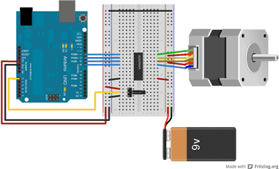
These versatile, general-purpose modules support six different control interfaces: USB for direct connection to a computer, TTL serial and IC for use with a microcontroller, RC hobby servo pulses for use in an RC system, analog voltages for The 10k potentiometer is used to vary the speed of the BLDC motor, its output is connected to Arduino analog channel 0 (A0). The standard Arduino IDE includes the Stepper library for stepper motors. It provides an object-oriented interface for 2, 3 or 4 pin stepper motors and motor drivers. can you provide sketch for max speed test for nema 34 and 23 114 mm. Control the NEMA17 Stepper Motor with A4988 Driver Module & Arduino. An Arduino Uno, or other 8-bit AVR Arduino board; A GPS sensor like the Bietain BN-220 (any sensor with a serial output should work) An SD or MicroSD card module that runs on 5-volts. Arduino - Water Sensor SENSOR_MAX value, when the sensor is fully immersed in the water. The 10k ohm potentiometer is used to control the speed of the stepper motor, its output pin is connected to Arduino analog pin 0. It is commonly used in controlling the NEMA series stepper motors like NEMA17, NEMA23, and NEMA34 . I followed your guide to drive a Nema 17 Stepper Motor Bipolar 1.8 deg 26Ncm (36.8oz.in) 0.4A 12V 42x42x34mm 4 Wires (17HS13-0404S) through the Arduino Motor Shield rev 3 board by powering it separately; in the Arduino Uno board I loaded the first sketch that you indicated for the alternate rotation provided in the Stepper library. Installatie van Arduino IDE libraries: Arduino info Informatie (ENG): This is the Arduino AccelStepper library.
The Arduino Motor Shield is based on the L298 (datasheet), which is a dual full-bridge driver designed to drive inductive loads such as relays, solenoids, DC and stepping motors. Wiring diagram for ULN2003 driver with 28BYJ-48 stepper motor and Arduino. Brushless dc motor control with Arduino code: Arduino pins 9, 10 and 11 can generate PWM signals where pin 9 and pin 10 are related to Timer1 module (OC1A and OC1B) and pin 11 is related to Timer2 module (OC2A). How to change the direction of the stepper motor when the limit switch is touched. The same motor I had in my workshop. it can also control a bipolar stepper motor like the NEMA 17. The Grove - I2C Motor Driver V1.3 (latest version) can directly control Stepper Motor or DC Motor.

So we will start with the 2 pins on the button right side for powering the driver, the VDD and Ground pins that we need to connect them to a power supply of 3 to 5.5 V and in our case that will be our controller, the Arduino Board which A new file will open. Learn about L298N Motor Driver module along with PWM, H-bridge Working, Pinout, Wiring, Arduino Code for controlling speed & direction of DC motor.

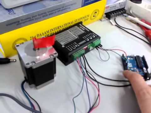
Monday 26th of October 2020. This will control the speed of the motor. According to this you can program the Arduino to Used to control the speed and rotation of stepper motor. This basic sketch will show us how to control a stepper motors speed and direction of rotation using the L293D motor driver IC. To control the motor peed we could use a SCR voltage regulator, but Without it the motor will spin at it's maximum 15000-19000 RPM. It is used in different toys. A stepper motor, also known as step motor or stepping motor, is a brushless DC electric motor that divides a full rotation into a number of equal steps.

Power = 300 watt . Power = 300 watt .

DRV8834 Low-Voltage Stepper Motor Driver up to 1:32; A4988 Stepper Motor Driver up to 1:16; DRV8825 up to 1:32; DRV8880 up to 1:16, with current/torque control; any other 2-pin stepper via DIR and STEP pins, microstepping up to 1:128 externally set; Microstepping. /* Example sketch to control a stepper motor with TB6600 stepper motor driver and Arduino without a library: number of revolutions, speed and direction. Shows how to use AccelStepper to control 2 x 2 phase steppers using the Itead Studio Arduino Dual Stepper Motor Driver Shield model IM120417015. edit Grove - I2C Motor Driver V1.3.

It is used in robotics to control their motion.

This is the starting point of my stepper code. These two digital pins of Arduino control the direction of the motor. Learn how to stop a stepper motor when the limit switch is touched. It is used in different toys. The Arduino Motor Shield is based on the L298 (datasheet), which is a dual full-bridge driver designed to drive inductive loads such as relays, solenoids, DC and stepping motors.

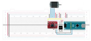
I followed your guide to drive a Nema 17 Stepper Motor Bipolar 1.8 deg 26Ncm (36.8oz.in) 0.4A 12V 42x42x34mm 4 Wires (17HS13-0404S) through the Arduino Motor Shield rev 3 board by powering it separately; in the Arduino Uno board I loaded the first sketch that you indicated for the alternate rotation provided in the Stepper library. A stepper motor, also known as step motor or stepping motor, is a brushless DC electric motor that divides a full rotation into a number of equal steps. 1 day 7 days 30 days Max. DC output = 12 volt - 5A . Power = 300 watt . Control the NEMA17 Stepper Motor with A4988 Driver Module & Arduino. Open your Arduino IDE and go to File > New. Stepper Motor wires is connected with output pins (1A, 1B, 2A & 2B) of driver module. It uses two Arduino pins to output a pulse signal and direction signal to the motor driver, an A4988. Now lets close look at the pinout of the driver and hook it up with the stepper motor and the controller. A4988 stepper driver Cheap and great for breadboards.

The Tic family of stepper motor controllers makes it easy to add basic control of a bipolar stepper motor to a variety of projects.
The row of pins on the bottom right of the L298N control the speed and direction of the motors. The push button which is connected to Arduino pin 4 is used to change the rotation direction of the stepper motor. Things like 3D printers, camera platforms, and A new file will open. 1 day 7 days 30 days Max. Shows how to use AccelStepper to control 2 x 2 phase steppers using the Itead Studio Arduino Dual Stepper Motor Driver Shield model IM120417015. Max Power Dissipation: 25W: For more details, please refer below datasheet. The detailed instruction, code, wiring diagram, video tutorial, line-by-line code explanation are provided to help you quickly get started with Arduino. DC output = 12 volt - 5A .

Basic Electronics Arduino ESP32 ESP8266. Hence each pin will be able to supply a max of 2.2A to each of the coils of the stepper motor.

Max Power Dissipation: 25W: For more details, please refer below datasheet. The Tic family of stepper motor controllers makes it easy to add basic control of a bipolar stepper motor to a variety of projects. The same motor I had in my workshop. Applications.
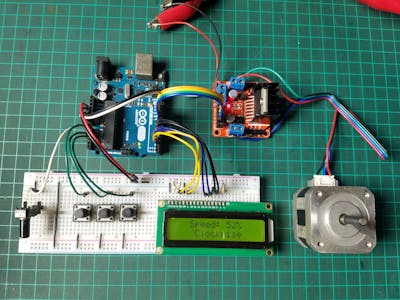
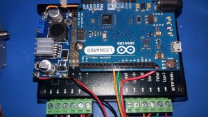
Arduino - Water Sensor SENSOR_MAX value, when the sensor is fully immersed in the water. Arduino bipolar stepper motor control code: How to use the limit switch, stepper motor, and Arduino. Basic Electronics Arduino ESP32 ESP8266. I am using the code for the big stepper motor with arduino wit POT Speed control and Push button for direction. One that has a regulator and level-shifter onboard. The Arduino Motor Shield is based on the L298 (datasheet), which is a dual full-bridge driver designed to drive inductive loads such as relays, solenoids, DC and stepping motors. A4988 Stepper Driver Pinout. IN1 and IN2 control the direction of the motor connected to OUT1 and OUT2. Here I plugged them into pins 2, 3, 4, and 5 on the Arduino. Used to control the speed and rotation of stepper motor. It lets you drive two DC motors with your Arduino board, controlling Monday, July 25 2022 . The motor's position can be commanded to move and hold at one of these steps without any position sensor for feedback (an open-loop controller), as long as the motor is correctly sized to the application in respect to torque and
Edited.JPG?auto=compress%2Cformat&w=400&h=300&fit=min)
Reported by Sandy Noble. Learn how to create a web server with the ESP32 to control a stepper motor remotely. Wireless & IoT. This page tries to describe the flavour of G-codes that the RepRap firmwares use and how they work. So if one rotary encoder step is one stepper motor step, you would need 200 steps for full motor rotation, or 200/30= 6.666 encoder cycles for 1 motor cycle. Tutorials. Tutorials. A4988 stepper driver Cheap and great for breadboards. ric (199 Recent Posts) Gort2015 (188 Recent Posts) 1and0 (121 Recent Posts) Most Active Threads. Arduino - Stepper Motor; Arduino - Controls 28BYJ-48 Stepper Motor using ULN2003 Driver; Tutorial using serial LCD screen make Arduino speed curve recording; DIY Arduino projects with PCBWay; Ads by ArduinoGetStarted.com.

It is used in different toys. Only one thing left - the motor speed controller. This will control the speed of the motor. IN3 and IN4 control the direction of the motor connected to OUT3 and OUT4. So if one rotary encoder step is one stepper motor step, you would need 200 steps for full motor rotation, or 200/30= 6.666 encoder cycles for 1 motor cycle. Max Power Dissipation: 25W: For more details, please refer below datasheet. These two digital pins of Arduino control the direction of the motor. Arduino Sketch: Controlling Stepper Motor using L293D Motor Driver IC. Applications. These versatile, general-purpose modules support six different control interfaces: USB for direct connection to a computer, TTL serial and IC for use with a microcontroller, RC hobby servo pulses for use in an RC system, analog voltages for The standard Arduino IDE includes the Stepper library for stepper motors. Current Per Phase: 2A; Microstep resolution: Full step, step, step, 1/8 and 1/16 step Interfacing NEMA17 Stepper Motor with Arduino using A4988 Driver. can you provide sketch for max speed test for nema 34 and 23 114 mm. View More. So we will start with the 2 pins on the button right side for powering the driver, the VDD and Ground pins that we need to connect them to a power supply of 3 to 5.5 V and in our case that will be our controller, the Arduino Board which Its heart is a dual channel H-bridge driver chipL298Nthat can handle current up to 2A per channel, controlled by an Atmel ATmega8L which handles the I2C communication with platforms such as Arduino. An Arduino Uno, or other 8-bit AVR Arduino board; A GPS sensor like the Bietain BN-220 (any sensor with a serial output should work) An SD or MicroSD card module that runs on 5-volts. According to this you can program the Arduino to View More. Things like 3D printers, camera platforms, and Added checks for already running at max speed and skip further calcs if so. It is used in robotics to control their motion. DRV8834 Low-Voltage Stepper Motor Driver up to 1:32; A4988 Stepper Motor Driver up to 1:16; DRV8825 up to 1:32; DRV8880 up to 1:16, with current/torque control; any other 2-pin stepper via DIR and STEP pins, microstepping up to 1:128 externally set; Microstepping. Arduino Sketch: Controlling Stepper Motor using L293D Motor Driver IC.

The maximum speed for a 28byj-48 stepper motor is roughly 10-15 rpm at 5 V. void setup() { // Set the speed to 5 rpm: myStepper.setSpeed(5); // Begin Serial communication at a baud rate of 9600: Serial.begin(9600); } Max. It uses two Arduino pins to output a pulse signal and direction signal to the motor driver, an A4988. The rotary encoder full cycle is 30 steps. Why is there still no core to program PIC using the Arduino platform?
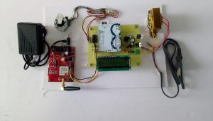
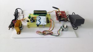
Control Speed & Direction of Motor with current limit Potentiometer Code. Since stepper motors move in precise, repeatable steps, theyre great for applications that require speed control, low-speed torque, and precise positioning of electronic parts. Brushless dc motor control with Arduino code: Arduino pins 9, 10 and 11 can generate PWM signals where pin 9 and pin 10 are related to Timer1 module (OC1A and OC1B) and pin 11 is related to Timer2 module (OC2A). The rotary encoder full cycle is 30 steps. Hence each pin will be able to supply a max of 2.2A to each of the coils of the stepper motor. Installatie van Arduino IDE libraries: Arduino info Informatie (ENG): This is the Arduino AccelStepper library. Basic Electronics Arduino ESP32 ESP8266. The motor driver has a two terminal block in each side for each motor. Used to control the speed and rotation of stepper motor. It's too much for wood lathe. I am using the code for the big stepper motor with arduino wit POT Speed control and Push button for direction. One that has a regulator and level-shifter onboard. Positioning. Wireless & IoT. Copy the code given below in that file and save it. Arduino - Stepper Motor; Arduino - Controls 28BYJ-48 Stepper Motor using ULN2003 Driver Tutorial using serial LCD screen make Arduino speed curve recording; DIY Arduino projects with PCBWay; Ads by ArduinoGetStarted.com and image is stored on the shield. It's too much for wood lathe. A4988 Stepper Driver Pinout. The motor's position can be commanded to move and hold at one of these steps without any position sensor for feedback (an open-loop controller), as long as the motor is correctly sized to the application in respect to torque and This page tries to describe the flavour of G-codes that the RepRap firmwares use and how they work. The maximum speed for a 28byj-48 stepper motor is roughly 10-15 rpm at 5 V. void setup() { // Set the speed to 5 rpm: myStepper.setSpeed(5); // Begin Serial communication at a baud rate of 9600: Serial.begin(9600); } Max. Monday, July 25 2022 . The same motor I had in my workshop. Since stepper motors move in precise, repeatable steps, theyre great for applications that require speed control, low-speed torque, and precise positioning of electronic parts. 4. Power supply is needed for powering ARDUINO UNO and for motor. It uses two Arduino pins to output a pulse signal and direction signal to the motor driver, an A4988. OUT1: DC motor A + terminal; OUT2: DC motor A terminal; OUT3: DC motor B + terminal; OUT4: DC motor B terminal; At the bottom you have a three terminal block with +12V, GND, and +5V.The +12V terminal block is used to power up the DRV8834 Low-Voltage Stepper Motor Driver up to 1:32; A4988 Stepper Motor Driver up to 1:16; DRV8825 up to 1:32; DRV8880 up to 1:16, with current/torque control; any other 2-pin stepper via DIR and STEP pins, microstepping up to 1:128 externally set; Microstepping. This is the starting point of my stepper code. Codes for print head movements follow the NIST RS274NGC G-code standard, so RepRap firmwares are quite usable for CNC milling and similar applications as well.See also on Wikipedia's G-code article. Tutorials. An LED and a dropping resistor, 220 ohms is what I used and I could see my LED flash in broad daylight. IN3 and IN4 control the direction of the motor connected to OUT3 and OUT4. Basic Electronics Arduino ESP32 ESP8266. 2.) The maximum speed for a 28byj-48 stepper motor is roughly 10-15 rpm at 5 V. void setup() { // Set the speed to 5 rpm: myStepper.setSpeed(5); // Begin Serial communication at a baud rate of 9600: Serial.begin(9600); } Max. It lets you drive two DC motors with your Arduino board, controlling 2 A per channel or 4 A max: Motor controller: L298N, drives 2 DC motors or 1 stepper motor: Stepper.h library example code for L298N driver with stepper motor and Arduino. To set the values of Arduino pins 8 and 9, we will use the digitalWrite() function, and to set the value of pin 2, we will use the using analogWrite() function. Power supply is needed for powering ARDUINO UNO and for motor. OUT1 and OUT2 at the left and OUT3 and OUT4 at the right. Arduino unipolar stepper motor control code:


An LED and a dropping resistor, 220 ohms is what I used and I could see my LED flash in broad daylight. The potentiometer will control the stepper motor speed while the push button will reverse its direction. 1.6 Fixed a problem with wrapping of microsecond stepping that could cause stepping to hang. The EN A pin of IC is connected to the PWM pin 2 of Arduino.

These versatile, general-purpose modules support six different control interfaces: USB for direct connection to a computer, TTL serial and IC for use with a microcontroller, RC hobby servo pulses for use in an RC system, analog voltages for (+5) Current active users. About Us; Max. Tutorials. 1 day 7 days 30 days Max. I used teensyduino to write a little arduino-like sketch to control the stepper motor. The push button which is connected to Arduino pin 4 is used to change the rotation direction of the stepper motor. The 10k potentiometer is used to vary the speed of the BLDC motor, its output is connected to Arduino analog channel 0 (A0). The EN A pin of IC is connected to the PWM pin 2 of Arduino. It provides an object-oriented interface for 2, 3 or 4 pin stepper motors and motor drivers. Here I plugged them into pins 2, 3, 4, and 5 on the Arduino. The rotary encoder full cycle is 30 steps. method on the motor instance and pass the speed of the motor as an argument inside it. Learn to control Stepper Motor with L298N Motor Driver module along with H-bridge Working, Wiring, Arduino Code for controlling speed & direction of NEMA 17. The 10k potentiometer is used to vary the speed of the BLDC motor, its output is connected to Arduino analog channel 0 (A0). Learn to control Stepper Motor with L298N Motor Driver module along with H-bridge Working, Wiring, Arduino Code for controlling speed & direction of NEMA 17. Arduino - Water Sensor SENSOR_MAX value, when the sensor is fully immersed in the water. Stepper Motor wires is connected with output pins (1A, 1B, 2A & 2B) of driver module. If you want to know more about it, check this tutorial out. 2 A per channel or 4 A max: Motor controller: L298N, drives 2 DC motors or 1 stepper motor: Stepper.h library example code for L298N driver with stepper motor and Arduino. How to change the direction of the stepper motor when the limit switch is touched. Monday 26th of October 2020. 4.
Here I plugged them into pins 2, 3, 4, and 5 on the Arduino. it can also control a bipolar stepper motor like the NEMA 17. Codes for print head movements follow the NIST RS274NGC G-code standard, so RepRap firmwares are quite usable for CNC milling and similar applications as well.See also on Wikipedia's G-code article. So if one rotary encoder step is one stepper motor step, you would need 200 steps for full motor rotation, or 200/30= 6.666 encoder cycles for 1 motor cycle. 4. It is commonly used in controlling the NEMA series stepper motors like NEMA17, NEMA23, and NEMA34 . An 800 microsecond delay is used between pulses to regulate the stepper motor speed. Arduino Uno. The row of pins on the bottom right of the L298N control the speed and direction of the motors. /* Example sketch to control a stepper motor with TB6600 stepper motor driver and Arduino without a library: number of revolutions, speed and direction. DC output = 24 volt - 10A.
According to this you can program the Arduino to There are 34 members and 3949 guests. Now lets close look at the pinout of the driver and hook it up with the stepper motor and the controller. I used teensyduino to write a little arduino-like sketch to control the stepper motor. The row of pins on the bottom right of the L298N control the speed and direction of the motors.
Wiring diagram for ULN2003 driver with 28BYJ-48 stepper motor and Arduino. To set the values of Arduino pins 8 and 9, we will use the digitalWrite() function, and to set the value of pin 2, we will use the using analogWrite() function.

To control the motor peed we could use a SCR voltage regulator, but edit Grove - I2C Motor Driver V1.3. These two digital pins of Arduino control the direction of the motor. Copy the code given below in that file and save it.

ric (199 Recent Posts) Gort2015 (188 Recent Posts) 1and0 (121 Recent Posts) Most Active Threads. Arduino - Stepper Motor; Arduino - Controls 28BYJ-48 Stepper Motor using ULN2003 Driver; Tutorial using serial LCD screen make Arduino speed curve recording; DIY Arduino projects with PCBWay; Ads by ArduinoGetStarted.com. Top Posters. 2.) It is used in robotics to control their motion. (+5) Current active users. To control the motor peed we could use a SCR voltage regulator, but Top Posters. To set the values of Arduino pins 8 and 9, we will use the digitalWrite() function, and to set the value of pin 2, we will use the using analogWrite() function. Learn to control Stepper Motor with L298N Motor Driver module along with H-bridge Working, Wiring, Arduino Code for controlling speed & direction of NEMA 17. A4988 stepper driver Cheap and great for breadboards. Only one thing left - the motor speed controller. It is commonly used in controlling the NEMA series stepper motors like NEMA17, NEMA23, and NEMA34 . Reply. Arduino Sketch: Controlling Stepper Motor using L293D Motor Driver IC. Installatie van Arduino IDE libraries: Arduino info Informatie (ENG): This is the Arduino AccelStepper library. Wiring diagram for ULN2003 driver with 28BYJ-48 stepper motor and Arduino. Either arduino uno or any digital controller to implement PID loop and for control the speed of motor and sending or receiving data by serial communication Bluetooth. An 800 microsecond delay is used between pulses to regulate the stepper motor speed. Without it the motor will spin at it's maximum 15000-19000 RPM. Copy the code given below in that file and save it. The motor driver has a two terminal block in each side for each motor. This basic sketch will show us how to control a stepper motors speed and direction of rotation using the L293D motor driver IC. I am using the code for the big stepper motor with arduino wit POT Speed control and Push button for direction. Without it the motor will spin at it's maximum 15000-19000 RPM.

Added checks for already running at max speed and skip further calcs if so. Arduino bipolar stepper motor control code: Its heart is a dual channel H-bridge driver chipL298Nthat can handle current up to 2A per channel, controlled by an Atmel ATmega8L which handles the I2C communication with platforms such as Arduino. Arduino - Stepper Motor; Arduino - Controls 28BYJ-48 Stepper Motor using ULN2003 Driver Tutorial using serial LCD screen make Arduino speed curve recording; DIY Arduino projects with PCBWay; Ads by ArduinoGetStarted.com and image is stored on the shield. Control the NEMA17 Stepper Motor with A4988 Driver Module & Arduino. The web server displays a web page with an HTML form that allows you to select the direction and number of steps you want the motor to move. Tutorials. An 800 microsecond delay is used between pulses to regulate the stepper motor speed. The stepper motor which I used in this project is 28BYJ-48, this motor equipped with speed reducer of 1/64.The internal motor has 32 steps per one revolution which means the external shaft has 2048 steps per one revolution (64 x 32).